
Shrinking Circuits, Meet Shaking Hands

DIY assistive technology for assembling miniaturized electronic prototypes

2020

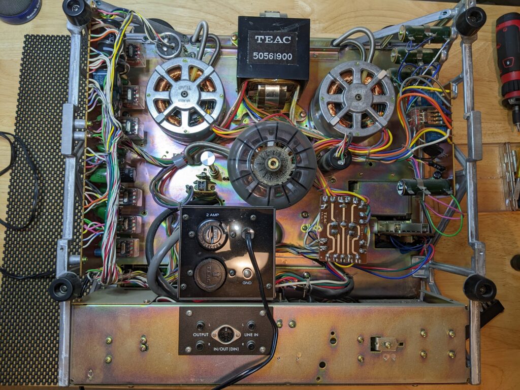
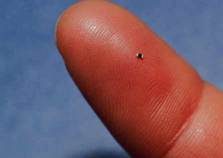
When I first started tinkering with electronics in the mid-20th century, most circuits used vacuum tubes. Over the 60 years since then, I’ve been privileged to witness the stunning progress in miniaturization, first with transistors, then basic integrated circuits, all the way to highly complex chips the size of your thumbnail with billions of transistors inside. To keep pace, small passive components — resistors and capacitors — shrank too. To build a prototype of a wearable device with a small size and weight, you have to be able to assemble these minuscule chips and components.

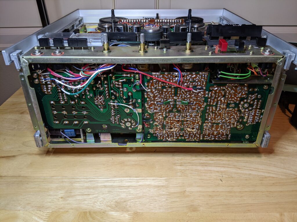
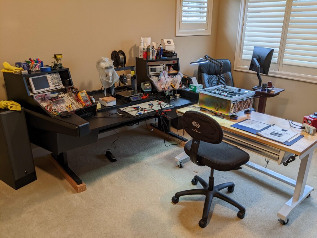
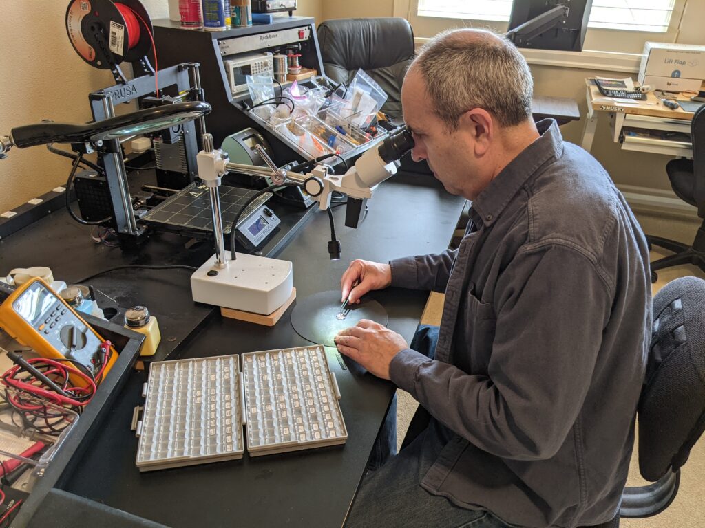
To assemble a circuit, I apply solder paste to pads on a printed circuit board using a laser-cut stencil. A boom microscope provides adequate magnification to see the parts, but the final step requires using a hand-held forceps to pick up and place the tiny components in exactly the right positions on the PC board. By the time I reached 70 years of age, the parts had shrunk to 0.040 x 0.020 inches size, with placement tolerances of 5 thousandths of an inch. And I found I could no longer grip, maneuver, and release the part from the forceps with the rock-steadiness required. Unwilling to give up, I hatched a DIY solution that restored my ability to place components at this new level of precision. More details are available after the photographs.

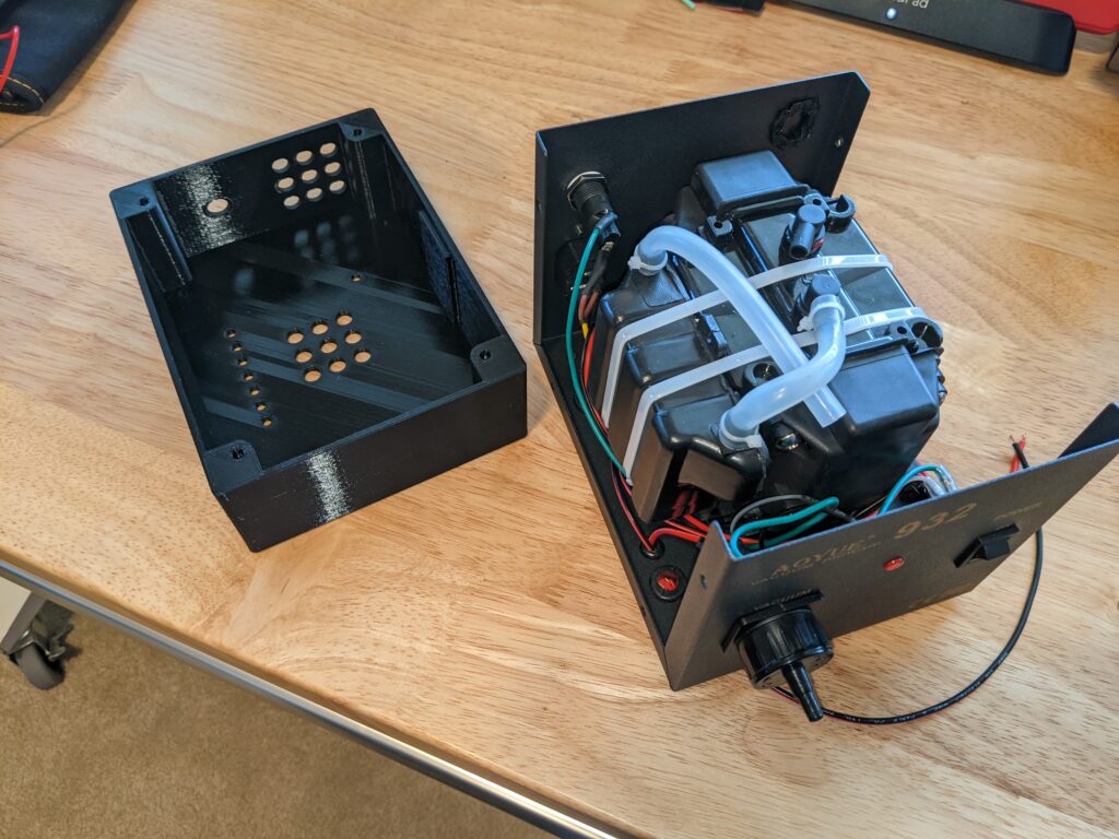
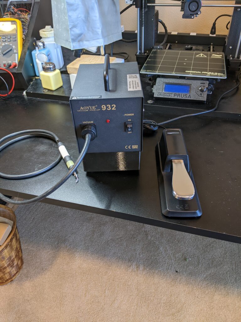
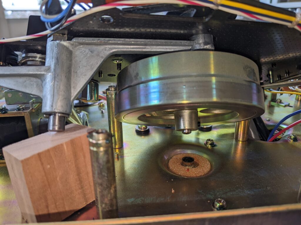
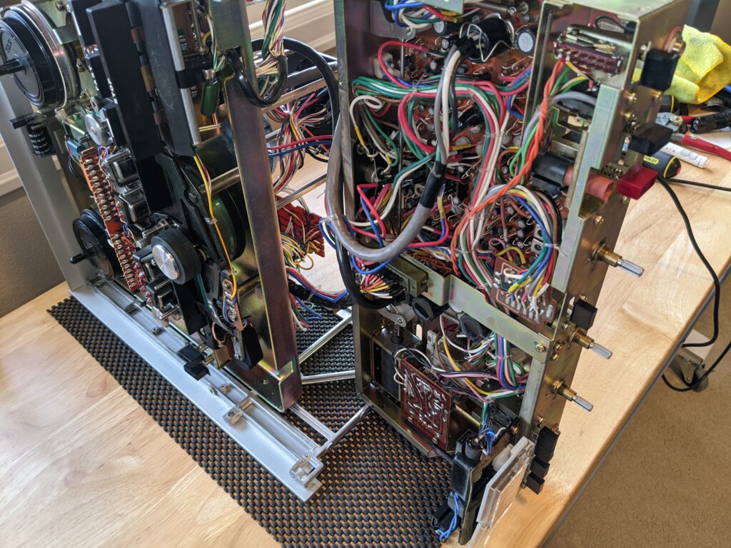
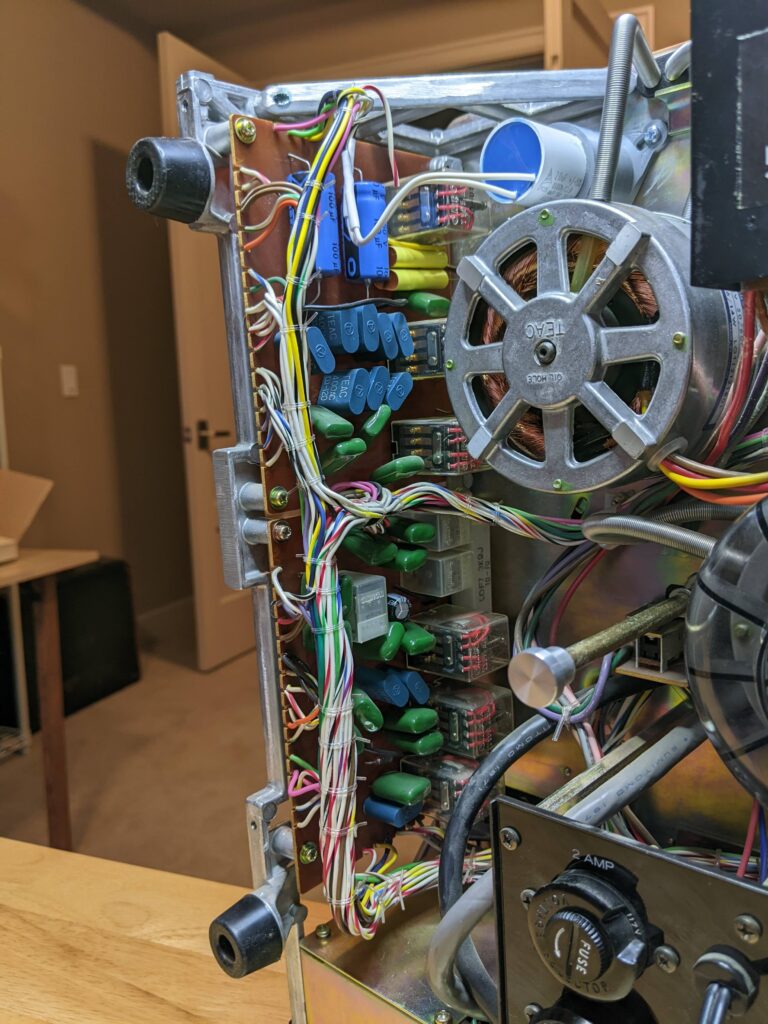
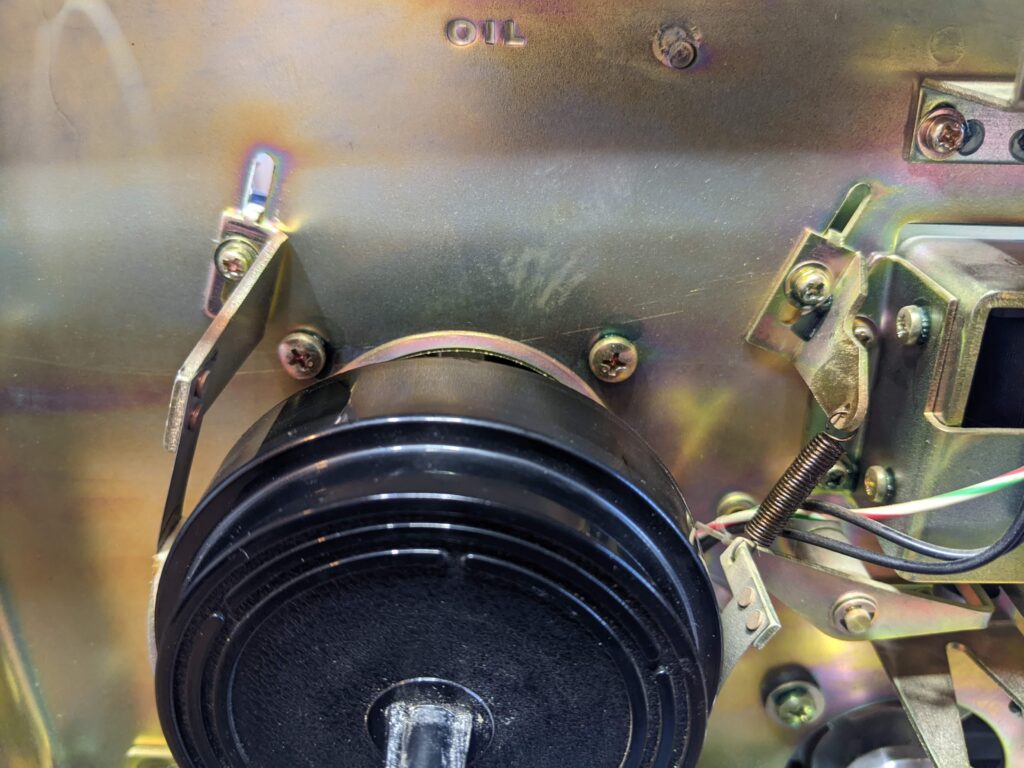
The first problem was one of crosstalk between two manual processes: moving the part into position over the PC board, and releasing pressure on the forceps at the right moment. The solution was to use a vacuum pick-up device instead of a forceps, and to reassign the function of releasing the vacuum to a foot pedal instead of my hand. From the photos, you’ll see how I started with an inexpensive vacuum pump, then added solenoid valves and associated circuitry to allow foot-pedal control of the vacuum.

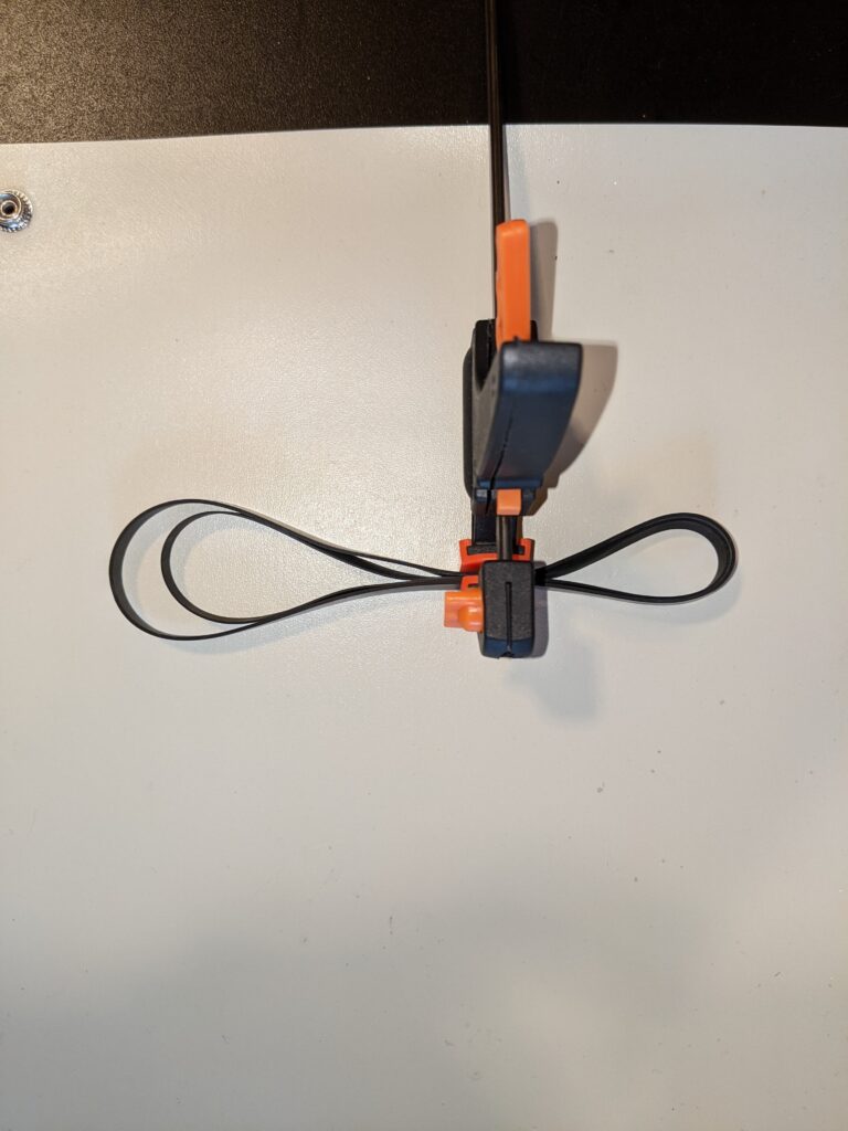
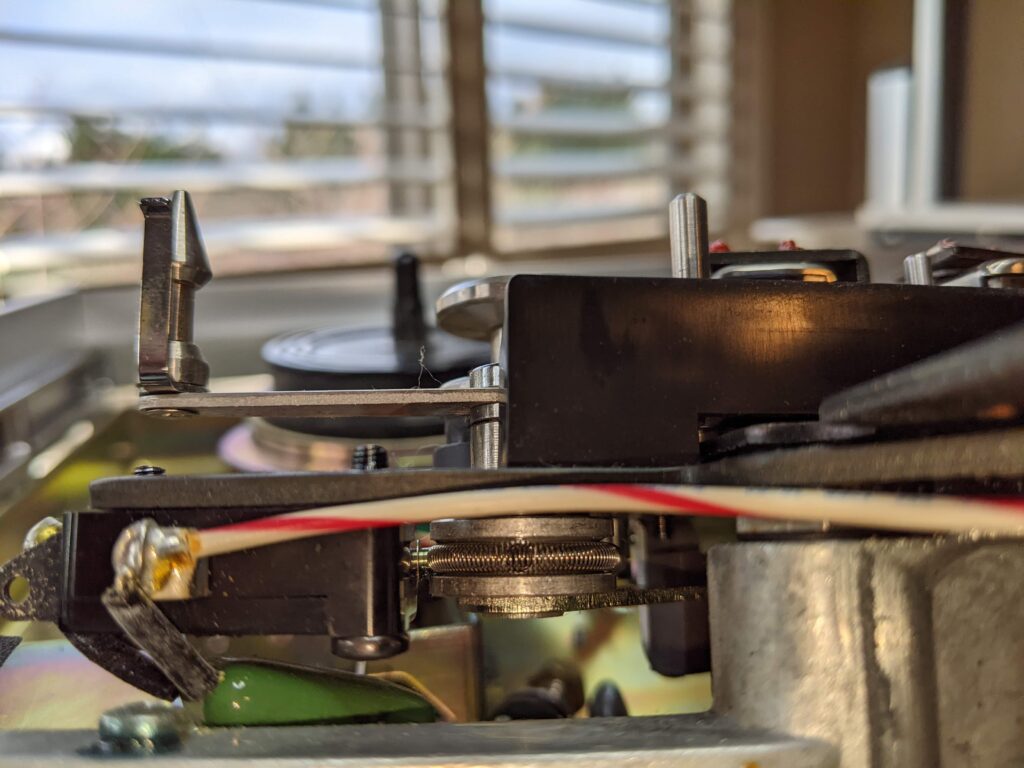
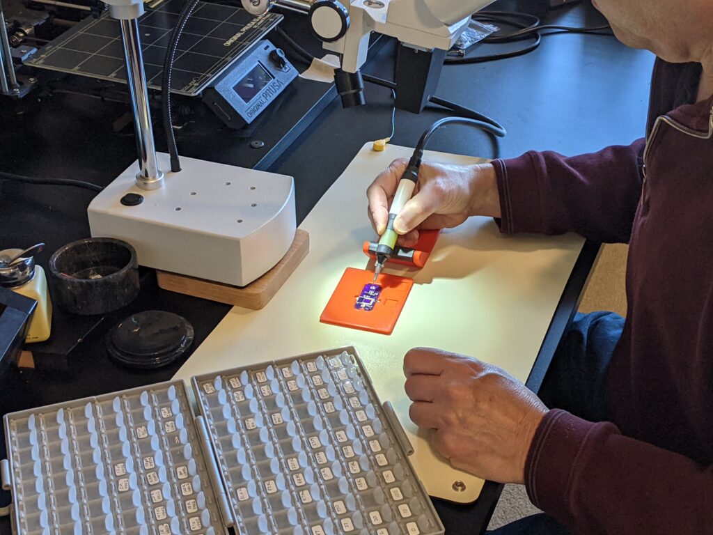
The second problem was that of tremor. With aging some neurons conduct impulses more slowly or even stop functioning, and a servomechanism with excessive delay in its control loop will overshoot and oscillate — and that causes tremor. The solution was to add a stabilizing fixture, with a fulcrum close to the PC board, and damping to reduce the oscillations. The stabilizing fixture was 3D printed, and its fulcrum area and the pickup tool were covered with rubber tubing selected for its damping characteristics.

Sensors for Seniors

2020-2022

Pandemic Project #1: Wireless sensors and gateway for CareBank

The Covid-19 pandemic was devastating to public health, but it also stimulated the development of new technologies hoping to re-establish our social connections. I met Claude Goodman in March 2020, learned of his CareBank project, and gladly took on the challenge of developing improved wireless sensors for that system.

The concept of a Bluetooth Low Energy module and motion sensor was not unusual, but long-range transmission, long battery life, and ease of battery replacement by an elder were more demanding requirements. We used BLE 5.1 and careful antenna design to extend the range and a low data rate to achieve >1yr of battery life. To change the battery, the user just slips off a silicone band (blue band in the rendering) and slides a new coin cell battery into a slot.

The next challenge was reliably relaying the sensor data to the CareBank servers in the cloud. While an up-to-date smartphone with an Internet data connection could do that job, it wasn’t realistic to assume every elder had such a smartphone always operational. As an alternative, I developed a Bluetooth-5-to-cellular gateway prototype. To maximize range, antenna placement was carefully optimized, and the communication link uses positive acknowledgement and retransmission to overcome dropouts. The gateway’s 3D-printed enclosure plugs into a standard USB charging brick, and the combination plugs into a wall outlet like a nightlight.

When it was time to manufacture a prototype run of 75 sensors, we hit one more challenge: the 2021 global semiconductor shortage. I learned how to source components from dwindling stocks in multiple countries and have the PCBs fabricated and assembled overseas. We were lucky; some key chips now have a one year lead time.

Rewinding by Half a Century

Restoring a 1971 vintage Teac A-4070 tape deck

2023

On the NextDoor social network, I found a post by Stephen Atkins looking for a nearby tape deck technician. There was a special meaning behind his request: Steve’s father, being blind, had preserved his memoirs and family events on reel-to-reel audio tape, not in photographs. When Steve’s Dad passed away 30 years ago, his recorder and tapes became lost in storage until recently.

From his online bio, I realized Steve himself was quite an expert with a long career in audio production. Still, he wisely decided not to just plug in the recorder, but to seek help. My own experience — side jobs during the ’60s in high school and college, at radio stations and a recording studio — was antiquated but relevant. With both the tape deck and me being relics from the same era, I thought we might be compatible.

The photo above shows the deck as it appeared when Steve brought it over, after 30 years of storage in its original shipping carton. The tape head cover had fallen off and its internal shield had come unglued, but otherwise things looked OK until I removed the case and began moving the mechanical parts by hand. The reel brakes were extremely tight and squeaky, the tape tension arms were frozen,  the level controls were nearly impossible to rotate, and some pushbutton switches were stuck. Inside, the drive belt had stretched with age and fallen completely off its pulleys.

Was I up for performing an operation on Steve’s prized, sentimental possession? I wasn’t quite sure until I found a scanned service manual for a later, but similar, model online. Having a schematic and assembly drawing, now I could understand the anatomy before undertaking surgery, so with the informed consent of the patient (actually the patient’s guardian) I went ahead.

The solid construction of the deck was reassuring. Weighing 50 pounds, it had a thick steel chassis, a cast aluminum frame, three big motors, a power transformer, and half a dozen printed circuit boards bristling with relays and solenoids. I opted not to power up the deck — which could damage irreplaceable components if there were short circuits — and to tackle the purely mechanical issues first.

The four tape heads and capstan/flywheel were supported by a thick steel plate. Since I didn’t want to unsolder the connections to the heads, I just detached the plate from the chassis and tilted it up, supported in on a wood block. That allowed enough access to disassemble and lubricate the tape tension arms, lubricate the capstan bearing, and mount the new drive belt. So far so good.

The electronic components most affected by aging — even worse when sitting unused — are electrolytic capacitors. Some restorers replace them all preemptively, while others just cross their fingers and turn on the power. Faced with more than 60 of them, I decided to start by replacing the two dozen most vulnerable ones — power supply filtering and motor capacitors — that could damage other parts if they failed.

The reel motor capacitor had 4 elements, housed in a can with its 5 tabs soldered to a PCB, and I was nervous about heating all those tabs at once while pulling the capacitor off. But fate smiled! Despite the otherwise stellar quality of the deck, the factory had failed to seat the capacitor fully onto the board. I was able to get needle nose pliers and diagonal cutters in to snip some of the tabs loose before desoldering.

The three capacitors housed in chassis-mounted cans were replaced with modern, smaller cylindrical capacitors. So I had some fun designing and 3-D printing plastic mounting brackets to adapt them to the original chassis mounting holes.

The remaining electrolytic capacitors were just a matter of patiently desoldering and replacing them on their respective printed circuit boards. I appreciated that the deck was obviously designed for repairability — by turning it to various positions, I could reach the bottom and top of most of the boards. Before reassembling, I cleaned all of the switches and level controls with spray-in contact cleaner, then re-lubed them until everything worked smoothly.

It was time for the Moment of Truth: power up — cautiously. A Variac was used, gradually increasing the line voltage while watching for any signs of overheating or smoke. Everything looked good, so it was time for mechanical and electrical alignment.

Mechanical alignment consisted of checking and adjusting the torque from the reel motors and brakes. The reel brakes were very tight and squeaky, even adjusted to their loosest setting. I solved this by “exercising” the brake springs, which had apparently stiffened in their old age (like people do). The motor torques were measured using spring scales, pulling on a string wrapped around the hub of a tape reel. Luckily, I was able to get everything within factory specs, and the deck demonstrated its rewinding, fast forwarding, reversing, and stopping prowess without snapping or spilling any tape.

Before performing electronic alignment, I cleaned and demagnetized the heads and guides. An oscilloscope was connected to the outputs, and a signal generator fed to the inputs.

A reference calibration tape was mounted, and the playback levels of prerecorded test tones on the tape were measured on the scope. Only minor adjustments had to be made to the playback head azimuth to peak the high-frequency response, and to bring left and right channels into phase match. A response plot showed the deck was achieving close to factory spec.

Since the primary intended use of the deck was to play back Steve’s archival tapes, didn’t attempt a full alignment for recording, but confirmed that recording does work.

Restoration complete, here’s the rejuvenated Teac A-4070 playing the #1 hit song of 1971!